EDPS (Exhaust Gas & Differential Pressure Sensor)
Principles - EDPS
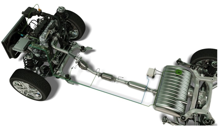
Task and Need
The sensors are required to provide the engine control units (ECU) with the necessary information regarding the exhaust gas pressures and the filling level of the diesel particle filter.
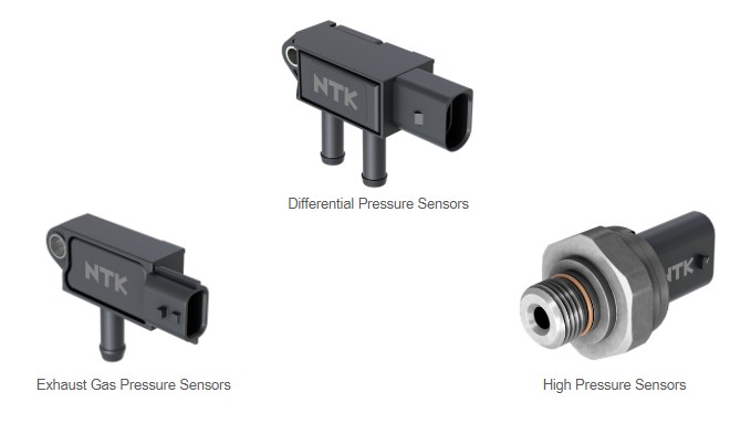
The high pressure sensor
The high pressure sensor measures the back pressure of the exhaust gases, the information is managed by the engine control unit (ECU) to monitor and protect the turbocharger unit.
Exhaust pressure monitoring prevents damage due to excessive back pressure in the exhaust system.
Areas of application
| Passenger cars | Trucks |
| Buses | Construction machines |
| All-terrain vehicles | Mining machines |
| Agricultural equipments | Special equipments |
Sensor element - Construction / Technology
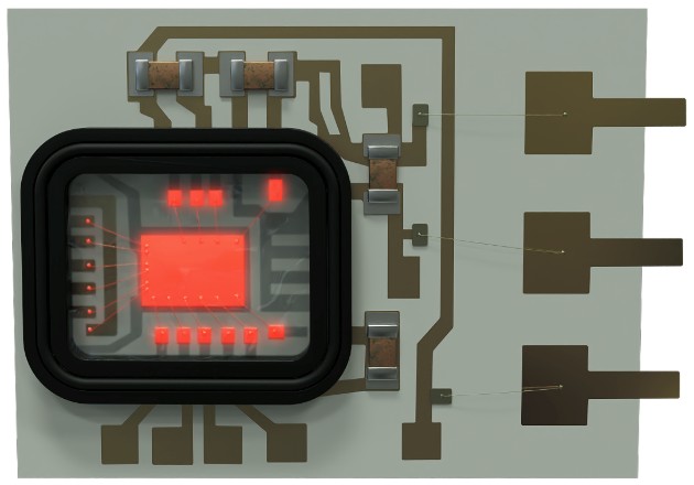
Construction and function: Sensor element I
Electric circuit
Ceramic substrate
Protective film
Silicon resin
Bonding
Construction and function: Sensor element II
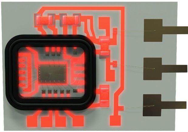
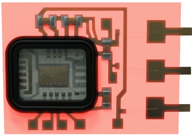
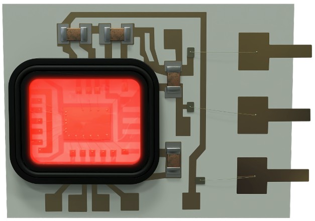
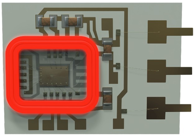
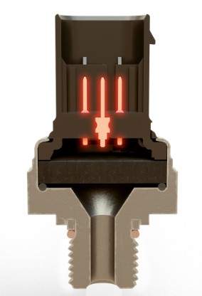
The sensor element converts a mechanical strain into an electric signal. This is achieved by using strain gauge resistors. This special type of resistor changes its resistance when subject to strain.
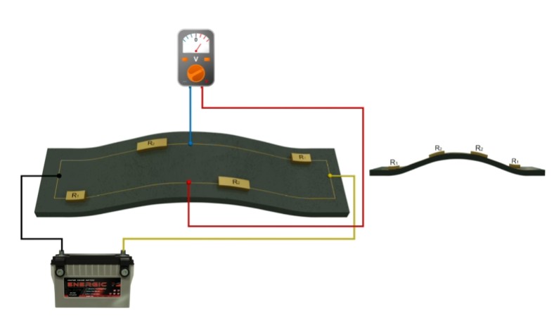
Four of these resistors are installed on a membrane and wired in a special circuit that is called “Wheatstone bridge”. This circuit is supplied with 5V voltage. If the membrane is now stretched by pressure, two resistors in the circuit are stretched and two resistors are compressed, which changes their resistance. This also changes the voltage of the entire circuit. This voltage change is transmitted to the engine control unit (ECU) by the signal wire which is connected to the two measuring points in the circuit.
In this animation, the engine control unit (ECU) has been replaced by a multimeter so that the change in voltage on the signal wire can be seen.
DPS - Construction / Technology
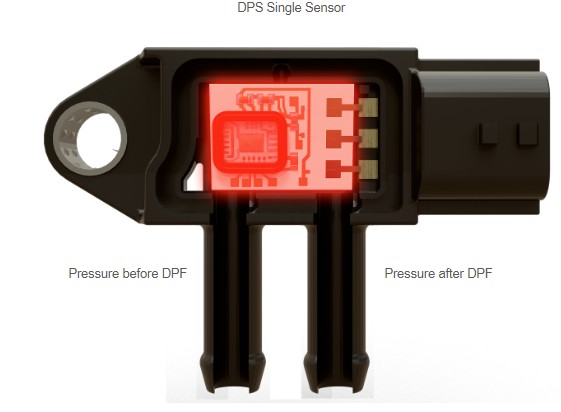
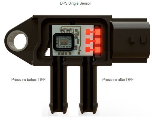
Construction and function: DPS Single Sensor I
Sensor element
| Supply voltage | 5 V ± 0,5 V |
| Operating temperature area | -40 °C to 125 °C |
| Response time | 1,5 ms |
| Maximum pressure | ±400 kPa (+30 °C for 5 s) |
Housing
| Supply voltage | 5 V ± 0,5 V |
| Operating temperature area | -40 °C to 125 °C |
| Response time | 1,5 ms |
| Maximum pressure | ±400 kPa (+30 °C for 5 s) |
ECU connection
| Supply voltage | 5 V ± 0,5 V |
| Operating temperature area | -40 °C to 125 °C |
| Response time | 1,5 ms |
| Maximum pressure | ±400 kPa (+30 °C for 5 s) |

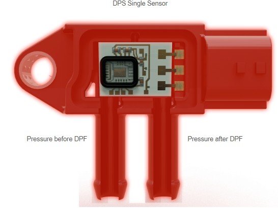
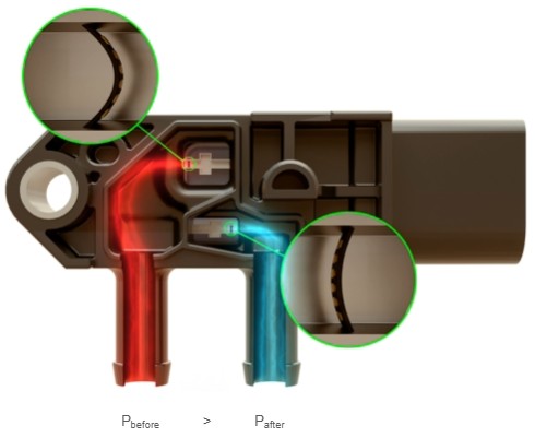
Construction and function: DPS Single Sensor II
P before < P after
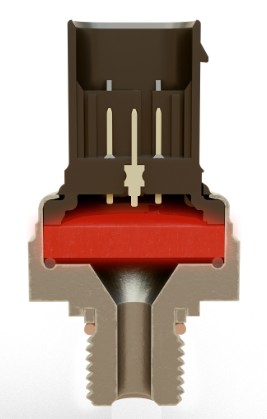
The DPS single sensor uses one sensor element that is connected to both connecting pipes. So the pressure element is effected from the pressure of both sides. This means that the differential pressure between the two pipes is measured and immediately transmitted to the engine control unit (ECU).
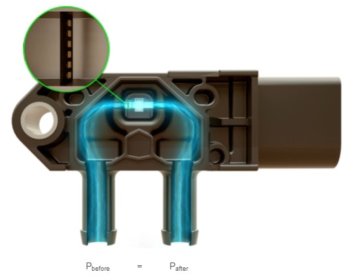
P before = P after
The DPS single sensor uses one sensor element that is connected to both connecting pipes. So the pressure element is effected from the pressure of both sides. This means that the differential pressure between the two pipes is measured and immediately transmitted to the engine control unit (ECU).
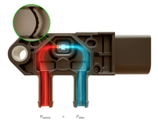
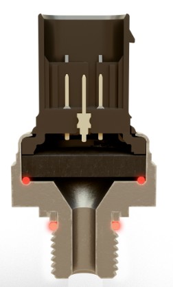
P before > P after
The DPS single sensor uses one sensor element that is connected to both connecting pipes. So the pressure element is effected from the pressure of both sides. This means that the differential pressure between the two pipes is measured and immediately transmitted to the engine control unit (ECU).
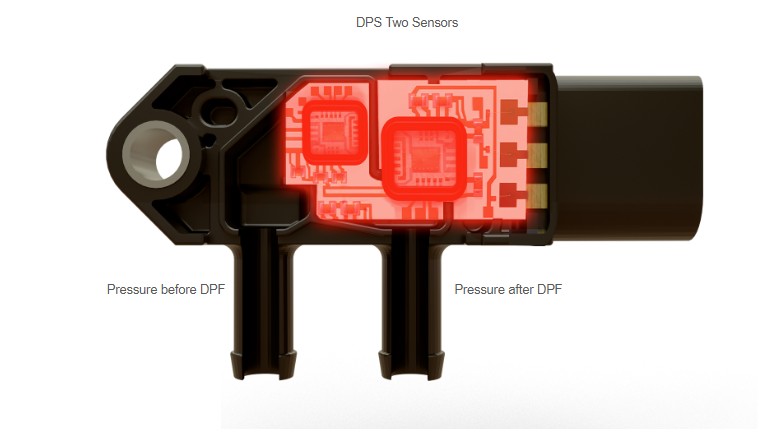
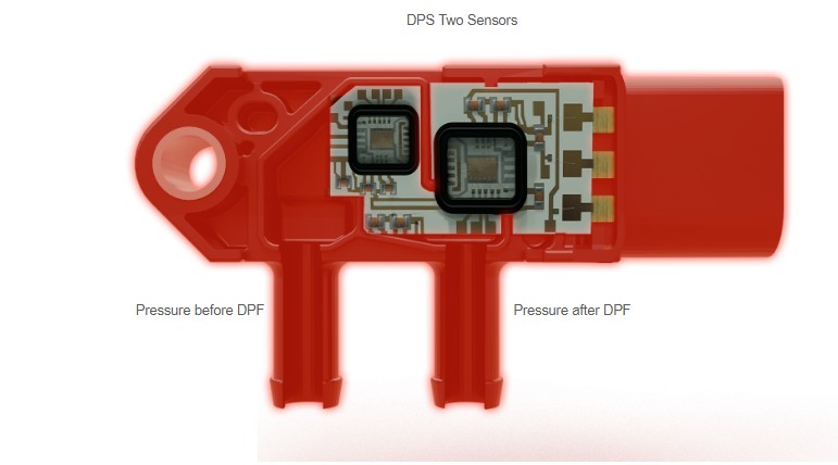
Construction and function: DPS Double Sensor
Two sensor elements
| Supply voltage | 5 V ± 0,5 V |
| Operating temperature area | -40 °C to 125 °C |
| Response time | 1,5 ms |
| Maximum pressure | ±400 kPa (+30 °C for 5 s) |
Housing
| Supply voltage | 5 V ± 0,5 V |
| Operating temperature area | -40 °C to 125 °C |
| Response time | 1,5 ms |
| Maximum pressure | ±400 kPa (+30 °C for 5 s) |
ECU connection
| Supply voltage | 5 V ± 0,5 V |
| Operating temperature area | -40 °C to 125 °C |
| Response time | 1,5 ms |
| Maximum pressure | ±400 kPa (+30 °C for 5 s) |
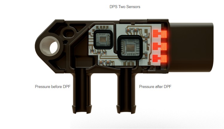
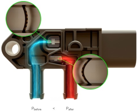
P before < P after
The DPS double sensor uses two sensor elements each of which is connected to one of the two connecting pipes. So the pressure element is effected from the pressure of one side only. The differential pressure of the two sensor elements is then calculated by the sensor's evaluation electronics and passed on to the control unit.
This technology is used to determine the differential pressure even more precisely.
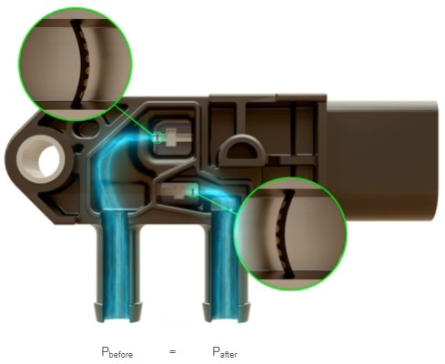
P before = P after
The DPS double sensor uses two sensor elements each of which is connected to one of the two connecting pipes. So the pressure element is effected from the pressure of one side only. The differential pressure of the two sensor elements is then calculated by the sensor's evaluation electronics and passed on to the control unit.
This technology is used to determine the differential pressure even more precisely.
P before > P after
The DPS double sensor uses two sensor elements each of which is connected to one of the two connecting pipes. So the pressure element is effected from the pressure of one side only. The differential pressure of the two sensor elements is then calculated by the sensor's evaluation electronics and passed on to the control unit.
This technology is used to determine the differential pressure even more precisely.
EPS - Construction / Technology
EPS - Construction and function
Sensor element
Construction / Technology - EPS
Supply voltage | 5 V ± 0,5 V |
Operating temperature area | -40 °C to 125 °C |
Response time | 1,5 ms |
Maximum pressure | ±400 kPa (+30 °C for 5 s) |
Housing
Construction / Technology - EPS
Supply voltage | 5 V ± 0,5 V |
Operating temperature area | -40 °C to 125 °C |
Response time | 1,5 ms |
Maximum pressure | ±400 kPa (+30 °C for 5 s) |
ECU connection
Construction / Technology - EPS
Supply voltage | 5 V ± 0,5 V |
Operating temperature area | -40 °C to 125 °C |
Response time | 1,5 ms |
Maximum pressure | ±400 kPa (+30 °C for 5 s) |
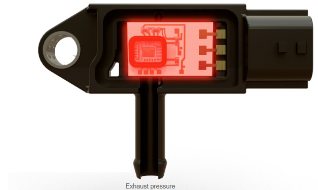
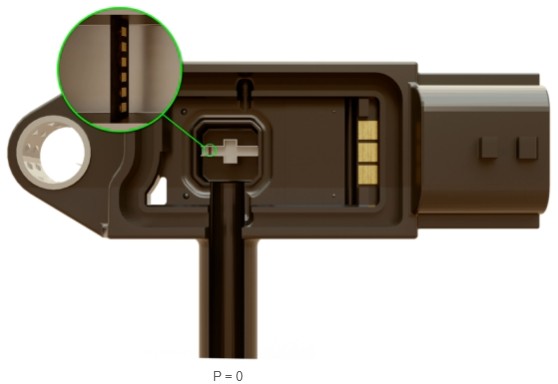
P = 0
Construction and function
The EPS sensor is used at points where only one pressure needs to be measured. It has only one connection tube, which is connected to one sensor element.
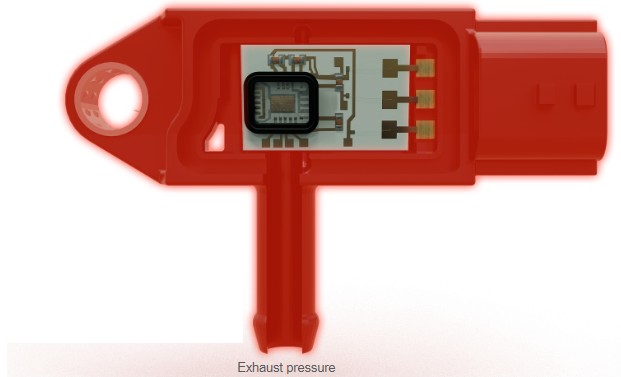
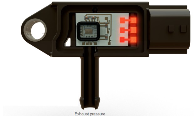
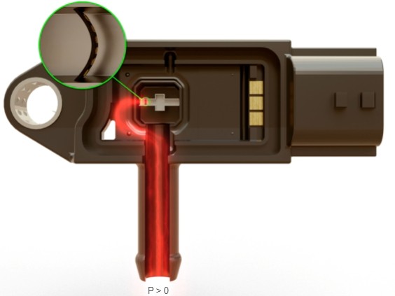
P > 0
Construction and function
The EPS sensor is used at points where only one pressure needs to be measured. It has only one connection tube, which is connected to one sensor element.
HPS - Construction / Technology
HPS - Construction and function
Supply voltage | 5 V ± 0,5 V |
Operating temperature area | -40 °C to 125 °C |
Response time | 1,5 ms |
Maximum pressure | ±400 kPa (+30 °C for 5 s) |
Plastic casing
Terminals
Pressure sensor
o-ring
Metal body
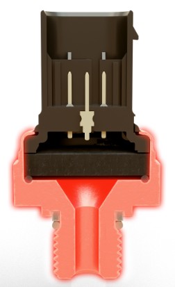
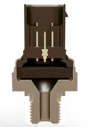
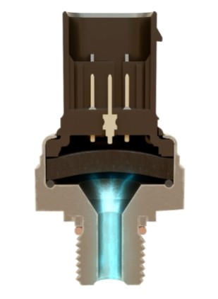
Low pressure
Similar to the EPS sensor, the HPS sensor is used to measure only one pressure. But in contrast to the EPS sensor, its housing and membrane are designed to be much more stable, so that significantly higher pressures can be measured.
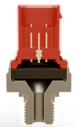
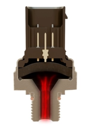
High pressure
Similar to the EPS sensor, the HPS sensor is used to measure only one pressure. But in contrast to the EPS sensor, its housing and membrane are designed to be much more stable, so that significantly higher pressures can be measured.
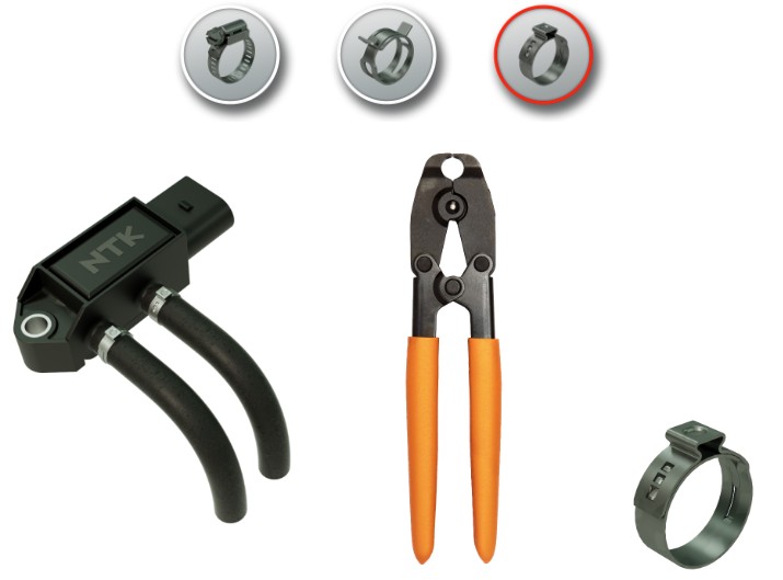
Installation hints
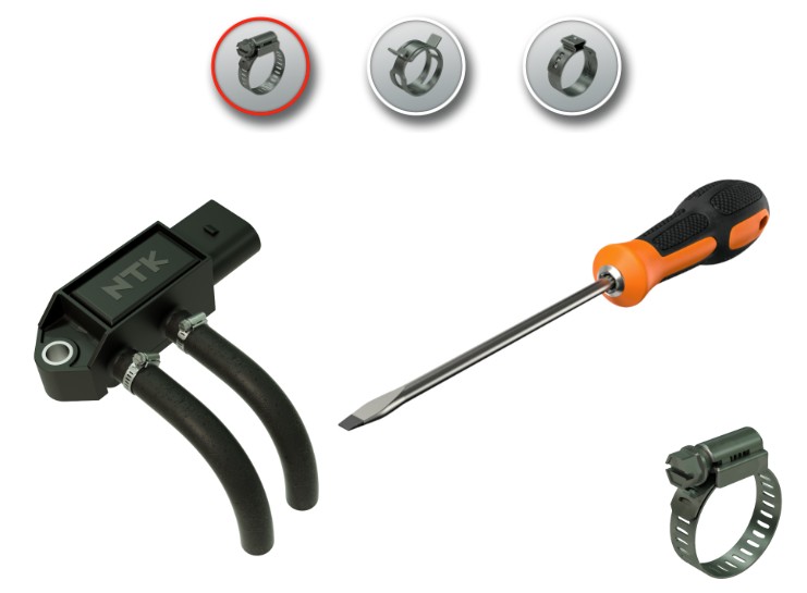
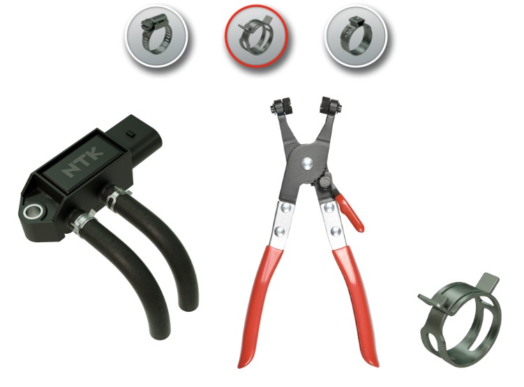
Tools
Depending on the vehicle, the hoses are secured to the sensor with different fastening clamps that require different tools.
Diagnosis
Symptoms in case of malfunction
- Loss of performance because the sensor does not detect the particle filters degree of saturation.
- The regeneration of the particle filter will not start.
- Particle indicator light comes on.
- Increased degree of contamination.
- Unnecessary filter regeneration and therefore shortening the lifetime of the DPF.
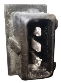
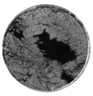
Corroded contacts
Water has penetrated
In this case water has penetrated the connector housing causing corrosion of the contacts. When the sensor is replaced, the connector seals, the connector contacts, and the wires between the connector and the engine control unit should be thoroughly checked.
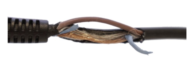
Broken / frayed cables
The cables have been damaged by external force. This can be caused by a strong pulling movement (cable laid too tightly / pulling on the wire while mounting) or by rotating parts (eg cable is rubbing against the v-belt). Therefore, pay attention to the correct cable routing during installation.
Damaged / porous connecting hoses
The connection hose is broken or porous and the exhaust gas pressure escapes from the system before it reaches the sensor element. Sometimes the connection hoses are very close to moving parts like the v-belt or to very hot parts like an exhaust pipe. Therefore it is important to check if all hose guides are still intact and connected.
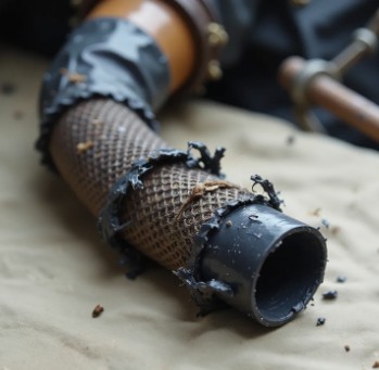
Clogged connecting hoses
The connecting hoses / pipes are clogged with soot deposits that build up in unfavorable operating conditions of the engine and settle in the exhaust system. The clogging changes the pressure conditions and the sensor measures incorrect pressures. The hoses should therefore always be checked for blockages and cleaned or replaced depending on the degree of clogging.
Diagnosis codes
| Code | Description | Possible Causes |
|---|---|---|
| P0471 |
|
|
| P2002/3 |
|
|
| P242F |
|
|
| P2455 |
|
|
| P2458 |
|
|
| P2459 |
|
|
| P2463 |
|
|
Testing EDPS sensors
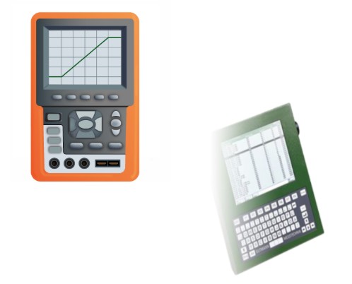
You can test all three sensor types (DPS, EPS and HPS) using the same test procedure. You can either use an oscilloscope or a diagnostic tool to display the sensor's output signal.
The prerequisite for the test is that the connector is still connected to the sensor and the hoses are removed from the sensors' connecting pipes. In addition, the ignition must be switched on so that the sensor is supplied with its operating voltage.
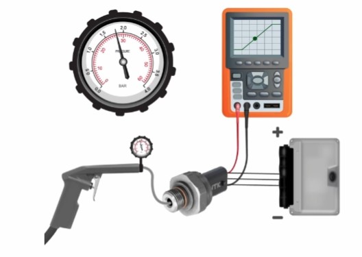
Testing EDPS sensors with an oscilloscope
- Connect the red measuring lead to the signal lead and the black measuring lead to the ground lead of the sensor.
- Set the voltage range and the time range of the oscilloscope so that the signal is clearly visible.
- Connect the air hose of the pressure pump to the connecting pipe of the sensor.
- Apply pressure to the sensor and observe the signal. The signal voltage must also increase with increasing pressure.
- With DPS sensors, please make sure to test both connecting pipes.
- The maximum pressure of 4 bar for DPS and EPS sensors and 30 bar for HPS sensors should not be exceeded.
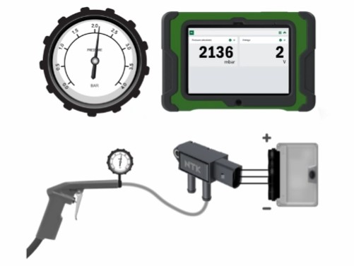
Testing EDPS sensors with a diagnostic tool
- Connect the diagnostic tool to the vehicle and select parameters “pressure” and “voltage” for the sensor you would like to check.
- Connect the air hose of the pressure pump to the connection pipe of the sensor.
- Apply pressure to the sensor and observe pressure and signal voltage on the diagnostic tool. The parameters must also increase with increasing pressure.
- With DPS sensors, please make sure to test both connecting pipes.
- The maximum pressure of 4 bar for DPS and EPS sensors and 30 bar for HPS sensors should not be exceeded.
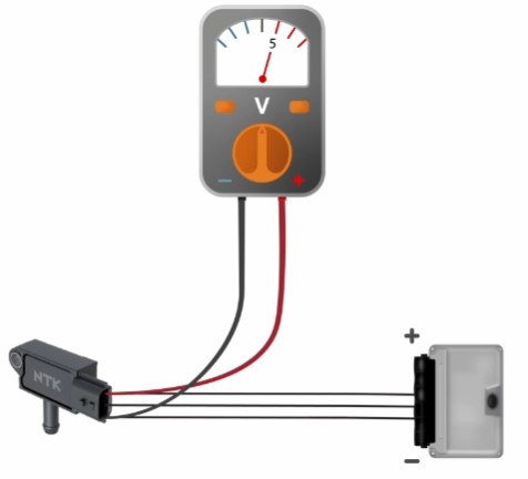
Testing the voltage supply
If there is no signal detectable with the oscilloscope or the diagnostic tool, there is most likely a problem with the power supply.
To check the power supply of the sensor you can measure the voltage between the plus and minus wire of the sensor. The set target value for the power supply is 5 V.
Testing the signal wire
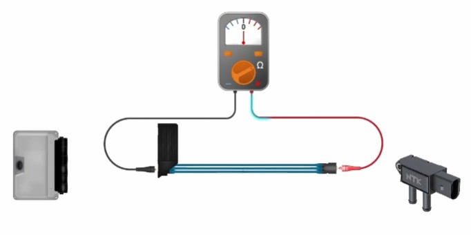
If the voltage supply is all right and no signal is visible on the oscilloscope or the diagnostic device, the signal wire should be checked for interruption.
To do this disconnect the connector from the engine control unit and the sensor to ensure that the wire can be measured in a current free state. Then connect the red test lead to the signal wire on the sensor connector and the black test lead to the signal wire on the engine control unit connector and measure the resistance of the wire.
The resistance can vary depending on the length and diameter of the wire but a resistance of approximately 1 Ohm is a normal value for a functioning cable.