Throttle body
Principles - Throttle body
Task and Need
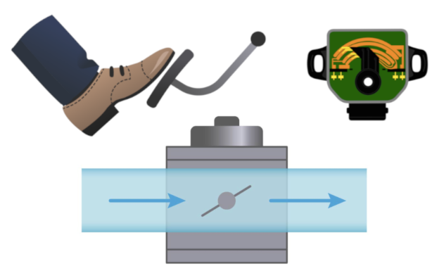
The throttle body is located in the intake tract of the combustion engine and controls the air flow that enters the engine.
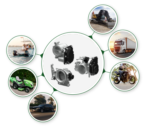
Need and areas of application
A throttle body is responsible for regulating the air in a combustion engine.
Depending on the engine concept, this serves different purposes.
| Petrol engines | Diesel engines |
|---|---|
| RPM (revolutions per minute) and power output are regulated here by dosing the fresh air. | They basically do not need a throttle body. In modern compression-ignition engines, throttling the intake air volume achieves precise control of exhaust gas recirculation and prevents the engine from shaking when the engine is switched off. |
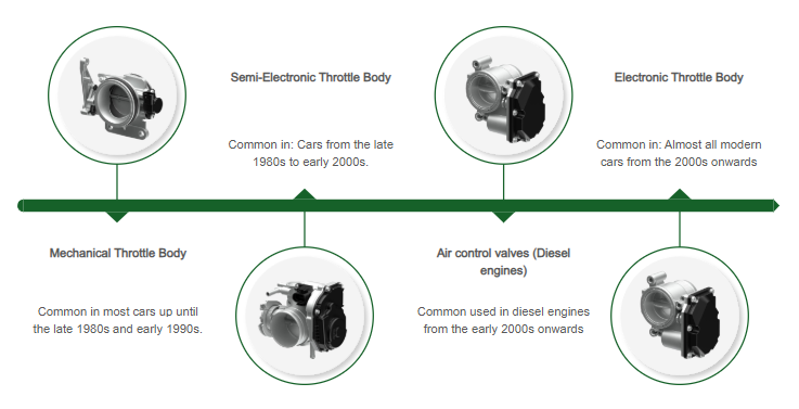
History / Evolution
Installation position
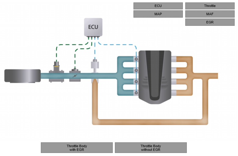
System overview and function
The throttle body has three main states, each corresponding to a specific operational scenario in the engine's intake system. These states regulate air intake and affect engine performance, fuel economy, and emissions. Here are the main states:
Transitions Between States
- Modern throttle bodies, particularly electronic throttle control (ETC) systems, adjust smoothly between these states based on sensor input (e.g., accelerator pedal position, engine load, and speed).
- These transitions are crucial for driveability, emissions control, and engine response.
Each state plays a vital role in engine operation, and faults in the throttle body can lead to poor performance or drivability issues.
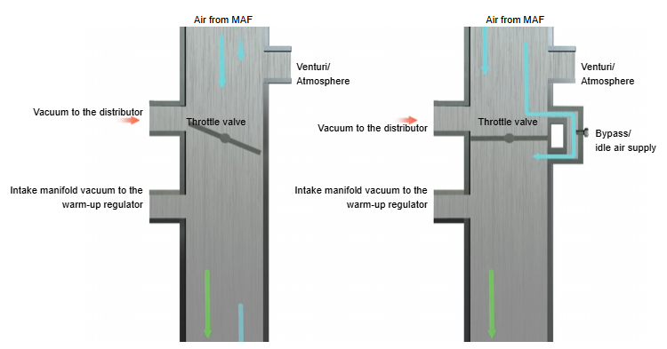
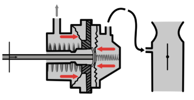
Idle state
The first main states of the throttle body: Idle State
1. Closed Throttle (Idle State)
- Description:
- The throttle plate is nearly closed, allowing minimal airflow into the intake manifold.
- This position is typical when the engine is idling or decelerating.
- Purpose:
- Maintains a small air passage to sustain combustion at idle speeds.
- The idle air control valve or throttle bypass mechanisms may adjust the airflow to stabilize the engine.
- Key Characteristics:
- High vacuum (low pressure) behind the throttle plate.
- Minimal fuel injection, optimized for maintaining idle speed.
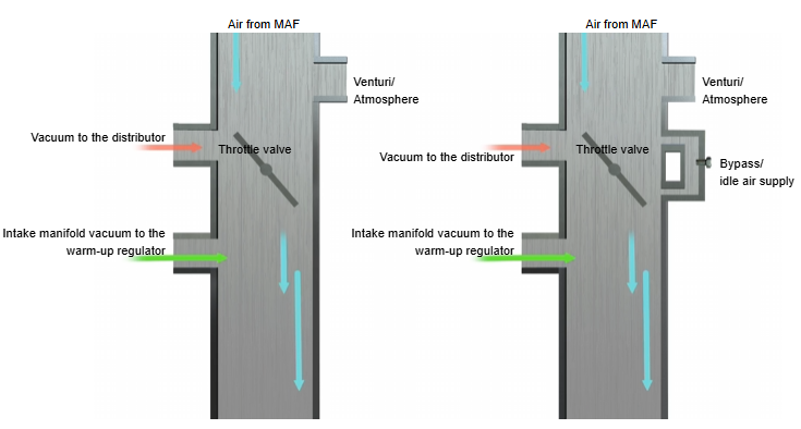
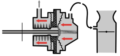
Part-Load state
The second main states of the throttle body: Part-Load State
2. Partially Open Throttle (Part-Load State)
- Description:
- The throttle plate opens partially in response to the driver's input (moderate accelerator pedal depression).
- This state is common during regular driving and cruising.
- Purpose:
- Provides a controlled amount of air to balance power and efficiency.
- Allows for moderate fuel injection to meet the power demand.
- Key Characteristics:
- Moderate vacuum in the intake manifold.
- Airflow increases proportionally to the throttle opening.
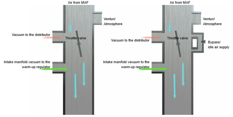
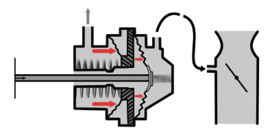
Wide open throttle
The third main states of the throttle body: Wide Open Throttle
3. Fully Open Throttle (Wide Open Throttle)
- Description:
- The throttle plate is completely open, allowing maximum airflow into the intake manifold.
- This state occurs during heavy acceleration or high-performance driving.
- Purpose:
- Maximizes power output by allowing the engine to ingest the largest possible volume of air.
- Corresponds to increased fuel injection and maximum engine performance.
- Key Characteristics:
- Intake manifold pressure approaches atmospheric pressure (minimal vacuum).
- High airflow rates result in peak engine output.
ECU
Ignition timing
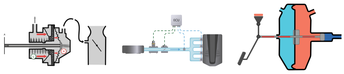
The negative pressure for the ignition timing is usually taken between the throttle valve and the engine in the intake manifold. This means that when the throttle valve is closed, i.e. at idle or at low throttle, the air drawn in by the engine cannot flow in easily and there is a high vacuum.
Double diaphragm ignition distributor - Overview
- Function:
- Combines centrifugal adjustment, early and late adjustment of the ignition timing.
- Advantage:
- Late ignition at idle reduces emissions through more complete combustion.
- Optimisation for idling, partial load and full load.
1. Idle (no load):
High under pressure → late adjustment.
2. Partial load (up to 1/4 throttle opening):
Early adjustment due to high under pressure in the carburettor.
3. Full load:
Both diaphragms in rest position → Only centrifugal adjustment active.
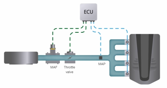
Air pressures upstream and downstream of the throttle valve (MAF MAP interaction)
The interaction of air pressures upstream and downstream of the throttle valve is central to controlling the air supply to the engine. Two important sensors, the Mass Air Flow (MAF) and the Manifold Absolute Pressure (MAP), record critical data here:
Pressure differences and typical values:
- Idle:
- Upstream of the throttle valve: atmospheric pressure (~1013 mbar).
- Behind the throttle valve: strong under pressure (~300-400 mbar).
- Partial load:
- Before the throttle valve: atmospheric pressure.
- Behind the throttle valve: Moderate vacuum (~600-800 mbar).
- Full load:
- Before the throttle valve: atmospheric pressure.
- Behind the throttle valve: Almost atmospheric (~950-1000 mbar).
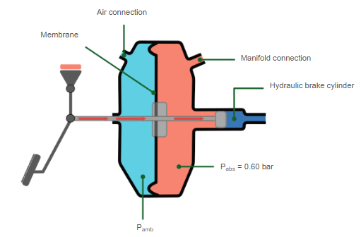
Brake booster
The throttle valve plays an important role for the brake booster, as it uses the under pressure in the engine's intake tract.
When the throttle valve is partially closed, a vacuum is created in the intake tract, which is necessary for the brake booster to function. This vacuum is used to increase the braking force and make the braking process easier for the driver.
Under pressure brake booster
- Use:
- Installed in most car brake systems.
- Functionality:
- Uses the under pressure to increase the braking force.
- Underpressure source:
- Petrol engine: Intake tract in the intake manifold.
- Diesel engine: Vacuum pump (0.5-0.9 bar).
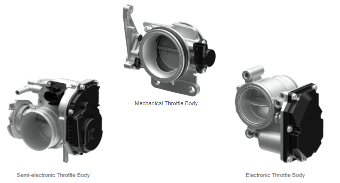
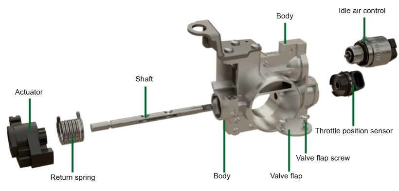
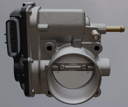
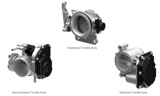
Construction / Technology - Throttle body
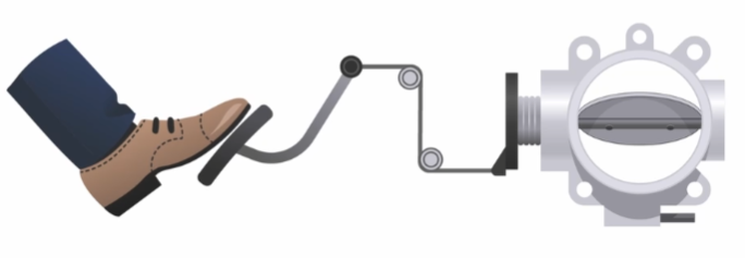
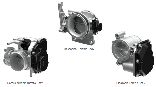
Mechanical Throttle Body - Construction and function
The throttle body is mechanically linked to the accelerator pedal and operated via a cable.
- The position of the throttle valve is transmitted to the control unit via an electronic signal.
Acceleration is controlled via the accelerator pedal, which is connected to the throttle valve via a Bowden cable.
- This controls the flap in the throttle valve and allows the required volume to pass through.
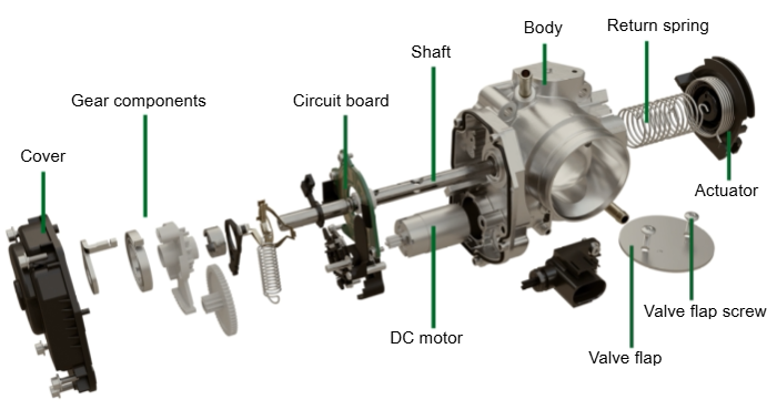
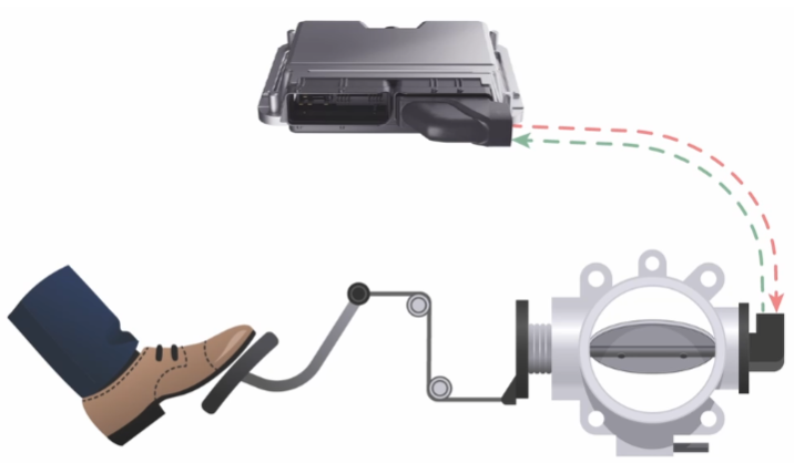
Semi-electronic Throttle Body - Construction and function
With an electromotive throttle valve, the position of the throttle flap is still adjusted mechanically using the Bowden cable.
- The position of the throttle valve is transmitted to the control unit via an electronic signal.
- Once all the parameters of the various sensors in the control unit have been synchronised, fine adjustment is carried out by a positioning motor on the throttle valve!
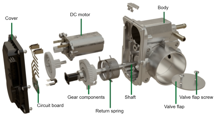
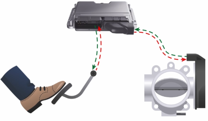
Electronic Throttle Body - Construction and function
With electronic throttle valves, there is no mechanical connection to the accelerator pedal. Instead, the driving request is detected by an electronic accelerator pedal.
- The engine management system continuously compares this signal with the data from the engine sensors in order to calculate the optimum position of the throttle valve.
- The electronic throttle valve is controlled exclusively by a servomotor, which is activated by the engine management system via a control signal.
Air control valves (Diesel) Throttle Body - Construction and function
In diesel engines, throttle valves are referred to an air control valves, which are available with or without integrated control electronics.
- They use an electric motor to throttle the intake air in order to precisely control exhaust gas recirculation and prevent disruptive vibrations when the engine is switched off.
Installation hints
Installation hints - Throttle body
- Find out the position of the throttle valve in the vehicle logbook (different manufacturers use different installation positions and throttle valve designs)
- Engine should be in cold condition
- Open the bonnet
- Remove attachments to the throttle valve
- Disconnect the connector / unhook the Bowden cable
- Unscrew the throttle valve
- Warning hint! Take care that nothing enters the open intake system
- Screw the new throttle valve back on (replace the seal!)
- Attach the connector / hook in the Bowden cable
- Refit the attachments to the throttle valve
- Close the bonnet
- If possible, re-learn the throttle valve with the diagnostic device!
Diagnosis
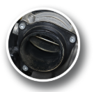
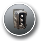
Malfunctions
Signs of a sooted/contaminated (1) or defective (2) throttle body:
- Engine does not start or runs unevenly.
- Reduced engine power.
- Idle problems (e.g. fluctuations or unsteady idling, delayed RPM reduction).
- ‘Engine fault’ warning light (Check Engine Light) has been lit.
- Throttle response problems.
- Higher fuel consumption


Defects
A defective throttle valve can have various causes that are mechanical, electrical or software-based in nature. Here are the most common causes:
Mechanical causes
Deposits and contamination
- Oil, dirt or soot can build up on the throttle valve, especially in vehicles with exhaust gas recirculation (EGR) or oil mist systems.
- Consequence: The flap no longer moves freely, which leads to idling problems or imprecise throttle response.
Wear
- After longer operation, mechanical parts such as the axle or the throttle control lever can wear out.
- Consequence: Inaccurate control or blockage.
Blockage
- Objects or defects in the intake manifold can block the movement of the flap.
- Consequence: Engine fault and loss of power.
Electrical causes
Defective throttle position sensors
- The throttle valve works with sensors (TPS - Throttle Position Sensors) that monitor the position and opening angle. A defect leads to misinterpretation of the control unit.
- Consequence: Malfunctions in the throttle response.
Actuator defects
- The electric motor that opens and closes the throttle valve can fail due to overheating or wear.
- Consequence: Lack of controllability of the flap.
Cable and connection problems
- Corroded, loose or broken cables between the throttle valve and the control unit can cause signal loss.
- Consequence: Interrupted communication and error codes.
Software problems
Missing calibration
- After a battery change or repairs, the throttle valve often needs to be relearned. Otherwise it will work inaccurately.
- Consequence: Fluctuating idling or poor throttle response.
Error in the control unit (ECU)
- A software error in the engine control unit can result in the throttle valve not being controlled correctly.
- Consequence: Irregular performance or complete breakdown.
Troubleshooting
A defective throttle valve can have various causes that are mechanical, electrical or software-based in nature. Here are the Recommended measures:
- Read out the fault code: You can use an OBD-II diagnostic device to determine the exact fault codes.
- Clean the throttle valve: Deposits can cause mechanical problems.
- Check connections: Check cables and plug connections for corrosion or damage.
- Programming the software: After a repair, it may be necessary to recalibrate the throttle valve.
- Authorised workshop: If the cause cannot be found, a visit to a workshop is recommended.
Trouble codes
The throttle valve is an essential component in modern combustion engines. Faults related to the throttle body are often indicated by specific fault codes in the on-board diagnostic (OBD) system. These codes are part of the OBD-II standard and usually start with ‘P’. Here are some common fault codes associated with the throttle body:
Common throttle valve error codes
| Error Code | Description |
|---|---|
| P0120 | Throttle/pedal position sensor (sensor A) - malfunction
|
| P0121 | Throttle/pedal position sensor - range/performance problem
|
| P0122 | Throttle/pedal position sensor (sensor A) - low input voltage
|
| P0123 | Throttle/pedal position sensor (sensor A) - high input voltage
|
| P0220 | Throttle/pedal position sensor (sensor B) - malfunction
|
| P0221 | Throttle/pedal position sensor (sensor B) - range/performance problem
|
| P0638 | Throttle valve actuator - control range/performance
|
| P2101 | Throttle valve actuator - control range/performance
|
| P2119 | Throttle valve - control blocked
|
| P2135 | Throttle/pedal position sensor - correlation faulty
|
Signal
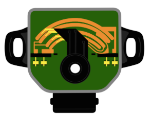
The throttle valve signal is crucial for the precise control of the air supply to the engine. It is generated and monitored by sensors and actuators that are integrated into the throttle valve.
The throttle potentiometer is an important component of the injection system in modern vehicles. It measures the position of the throttle valve, which regulates the air flow into the engine. The potentiometer sends an electrical signal to the engine control unit, which uses the information to optimally control the air-fuel mixture. This ensures efficient combustion and better engine performance. If the potentiometer is defective, this can lead to problems such as loss of power or uneven engine running.
Function:
A throttle potentiometer with an opposing signal supplies two voltages:
- Primary signal: The voltage increases in proportion to the opening of the throttle valve.
- Secondary signal: The voltage drops in proportion to the opening of the throttle valve (in the opposite direction).
Normal values of the signal:
- Throttle flap position:
- Closed: Approx. 0.5 volt (5-10 % of the maximum opening).
- Idle position: Approx. 10-15 %.
- Fully open: 4.5 volts (90-100 % of the maximum opening).
- Deviations:
- A deviation between sensor A and sensor B leads to error codes (e.g. P2135).
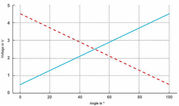
Signal graph
The signal diagram shows a throttle potentiometer with an opposing signal:
- Primary signal (blue): The voltage increases in proportion to the opening of the throttle valve (e.g. from 0.5 V at idle to 4.5 V at full throttle).
- Secondary signal (‘dotted red’): The voltage drops at the same time in the same ratio (from 4.5 V at idle to 0.5 V at full throttle).
The constant sum of both signals (5 V) enables a reliable plausibility check to detect errors or deviations.
Sensor A (linear) (blue)
Sensor B (invert) (red)
Typical problems with the signal
- Faulty signal values
- Causes:
- Wear of the sensor.
- Dirt on the throttle flap that affects the position.
- Cable problems (short circuit, corrosion).
- Symptoms:
- Engine stuttering.
- Problems with throttle response.
- Error messages such as ‘Check throttle valve system’.
- Causes:
- Signal interference
- Electromagnetic interference or faulty earth connections can lead to implausible signals.
- Solution: Check wiring and earth points.
- Discrepancy between sensor A and B
- Both sensors should work synchronously. A deviation leads to error codes such as P2135 (Signal correlation faulty).